By Mark Vrolijk, Product Marketing, CAE
Introduction
In today’s automotive world, digital transformation is rapidly reshaping every corner of the industry—but one area has remained surprisingly traditional: Body-in-White (BIW) assembly. While simulation tools have revolutionized stamping and crash testing, the actual assembly process still leans heavily on physical tryouts and late-stage corrections. That is, until now.
Keysight is unveiling a brand-new solution set to transform how engineers approach BIW assembly. Called simply Keysight Assembly, this new software promises to empower automotive manufacturers with early insight, seamless integration, and a dramatically more intuitive user experience.
To learn more, Mark Vrolijk, Keysight’s product marketing manager for the Virtual Manufacturing portfolio, sat down with San Gooroochurn, the product manager behind this next-generation simulation tool, for an in-depth conversation about what makes this solution so different—and why it’s arriving at just the right time for the automotive industry.
Mark: Hi San, thanks for joining us today. Could you start by telling a bit about your background and how your career led you to this point?
San: Starting from my educational background: I have a dual degree; a master’s in mechanical engineering from Central Lyon (ENISE, St. Etienne, France) and an MBA from Colorado Technical University (Colorado Springs, CO, USA).
I started my professional career in the manufacturing sector as a welder and workshop supervisor nearly 30 years ago. Along the way, I worked and acquired firsthand experience in many countries (Mauritius, France, Belgium and USA) and in many industries (Construction & Manufacturing, Steel Production, Automotive, Research & Development and Software).
I have been in the software industry for 18 plus years with ESI, now Keysight, using my past manufacturing, research and educational background to approach complex industrial challenges in pragmatic ways and to provide realistic modeling solutions to customers in various industries across disciplines.
Since 2022, I embarked in a new endeavor as a Senior Product Manager, working alongside a team of highly talented software developers, mechanical and materials engineers and UX designers to deliver the next generation Assembly Simulation Software, focused on providing an enhanced user-oriented software solution to customers for resolving real life assembly challenges related to Automotive Body In White Assemblies.
Today, we are proudly releasing the first version of Keysight Assembly, a simulation software tool which is a product of our hard work and the collaboration and guidance of our early adopters.
Mark: Great, now turning to today’s topic—for those who might not be too familiar with how automotive bodies are put together, can you walk us through the current BIW assembly process?
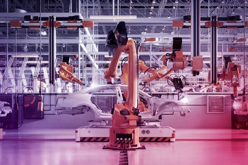
San: Sure. In today's automotive world, assembling the body structure—the Body-in-White—is primarily done using resistance spot welding. It's the standard method for joining sheet metal components, and even though there are new joining technologies being developed, spot welding is still the most important one because it's fast, reliable, and cost-effective.
The BIW is essentially the skeleton of the vehicle, made up of stamped steel or aluminum parts. These parts are brought together in robotic assembly lines, where arms equipped with spot welding guns fuse them together. The actual process involves pressing two or more overlapping sheets of metal with copper electrodes and running a high electrical current through them. The resistance at the contact point generates heat, and that’s what creates the weld. It happens in milliseconds, and one car can easily have over 3,000 of these welds.
It’s quick and works well at scale, but there are issues. Forming tolerances and springback can introduce gaps at the weld locations, and that can cause dimensional problems or inconsistent weld quality. So engineers are constantly trying to manage those small variations to keep everything in spec.
Mark: That definitely highlights the challenges. So where does simulation fit into all this today?
San: Simulation is already well-established in other parts of automotive manufacturing—like forming simulations for stamping or crash simulations for safety analysis—but when it comes to BIW assembly, simulation isn’t used as widely as people might expect. Some innovative OEMs are starting to adopt it, but the traditional approach still relies on physical try-outs.
Usually, engineers will wait until late in the development process when production-intent parts and fixtures are ready. They build up the body, measure the result, and then make adjustments. If distortion shows up at that point, it’s a problem. Fixing it can require redesigns, changes to welding sequences, or even modifications to the fixtures—and all that eats into budgets and could even potentially delay the start of production.
Mark: So how does your new solution change that picture?
San: Our goal with Keysight Assembly is to move those decisions much earlier in the process. With this software, engineers can simulate any sub-assembly of the Body-In-White, like doors, hoods, bodyside etc, in a virtual environment—well before any physical parts or tools exist.
It’s built to be useful at every stage. In the concept phase, you can use it with nominal CAD geometry to quickly setup the global production intent and explore different clamp and weld setups. Then, when forming simulation data becomes available, you can include realistic distortions like springback, which is critical for predicting gaps and internal stresses. Later on, once you have scanned components of even entire sub-assemblies, those can be imported as well to bring the simulation even closer to reality.
The beauty of it is that you’re working with the same model the whole way through, just updating it as better inputs become available. That means you’re not constantly starting over, and you can keep refining your understanding of how the body will behave. It really reduces surprises and lets you solve problems before they turn into production issues.
Mark: That sounds like a major shift. There are already some tools on the market, though. What sets this solution apart?
San: What really makes this tool different is how it’s been designed from the ground up with usability and accessibility at its core. Our goal was to empower assembly process engineers—not just experienced FEM users—to take control of virtual validation. A lot of existing tools in the market fall into one of two extremes.
On one end, you have highly advanced FEM-based platforms that offer strong predictive capabilities—but they’re also extremely complex. They require deep simulation expertise, long training cycles, and often a dedicated team just to operate them effectively. That creates a barrier for most body-in-white (BIW) manufacturing engineers who need quick, actionable insights and often lack (in-depth) FEM and meshing knowledge.
On the other end, there are simplified assembly tools designed to maximize ease of use. But these often over-simplify the real process, skipping critical details like material behavior, realistic gaps, or thermal distortions. As a result, they work well only for basic configurations, but their predictive value quickly breaks down in more complex or realistic setups, which is exactly when you need simulation the most.
Our solution is aiming for the right balance. It’s built with an assembly process-driven workflow that mirrors shop-floor logic—clamping, joining, measuring—and it features a graphical drag-and-drop interface that lets engineers define assembly cells and sequences just like they would in reality. Even complex lines can be configured in minutes.
At the same time, we’ve made sure it’s open and powerful enough for FEM experts, who can dive deeper when needed. They can access detailed solver parameters, material models, and mesh control to push the predictive boundaries and fine-tune results.
So whether you’re a manufacturing engineer needing quick insight or a simulation expert looking to optimize a process to the finest detail, Keysight Assembly assists you at any level—intuitive for newcomers, detailed for specialists, and predictive across the full spectrum of assembly complexity.
Mark: That’s impressive. Anything in the tool that deals with getting results earlier and faster compared to current practice?
San: Yes—and that’s actually one of the most important developments in the tool. In early phases of assembly process planning, accurate stamped part data or 3D scans often just don’t exist yet. Traditionally, engineers are forced to work with nominal CAD geometry—clean, perfect shapes that look great on screen but don’t reflect the realities of manufacturing.
But in the real world, stamped parts come with imperfections: springback, warping, surface waviness, you name it. These small deviations might seem minor, but when you try to clamp and weld them in an assembly, they can cause significant distortion. Gaps that form between parts are forcibly closed by clamps, generating hidden stresses. Once the structure is welded and then unclamped, these stresses are released—and that’s when unexpected distortions appear.
If you're only simulating the perfect nominal CAD shape, you miss all of that. The results might look fine, but they’re not highly predictive. That’s why we introduced a unique feature: realistic geometry generation. It creates non-nominal part shapes automatically using just three basic inputs: the part’s geometry, its material type, and thickness. That’s it—no need to be a stamping simulation expert or rely on detailed springback data.
This approach gives assembly engineers a powerful head start. They can generate plausible distorted shapes, entirely within defined tolerances, and use them to evaluate distortion effects much earlier in the process. That means they’re no longer dependent on the stamping team to move forward—they can explore and validate weld and clamp strategies on their own, weeks or even months earlier than before.
On top of that, we also support the import of full sub-assembly scans. That’s a huge benefit, especially for OEMs that outsource parts of their body structure. Instead of waiting for physical parts to arrive on-site, engineers can simply use scan data to simulate the assembly process digitally and validate results early.
By combining early, realistic input without needing stamping expertise and digital validation using scan data, we’re closing a critical gap in today’s development cycle—bringing actionable insights to the assembly engineer much earlier and with far greater realism.
Mark: What about materials and quality control? Are those supported too?
San: Definitely. We have a built-in automotive material database, so users don’t have to manually source or input material properties. That saves time and reduces setup errors.
And for quality control, there’s a virtual quality inspection cell (QC) inside the tool that works just like a real inspection station. It lets you measure dimensional deviations, internal stresses, clamp forces, and component gaps—both before and after welding. That data helps engineers apply the right countermeasures and improve overall assembly quality based on solid, physics-driven insights.
Mark: That’s quite a lot. I’m curious—how did you build all of this? Was it all developed in-house?
San: Actually, no. That’s another important part of the story. When we started, we didn’t just sit in a room and developed a product based on what we thought people wanted. We had a pretty novel concept in mind—a new way to approach assembly—but we weren’t sure how the industry would respond.
So we started by building a prototype that focused more on the graphical interface and workflow, rather than hardcore FEM. Then we went to some of the big OEMs to show them what we were thinking.
The feedback was overwhelmingly positive—but they also told us that what we had in mind wasn’t ambitious enough. So we teamed up with a few early adopters and really developed the product together.
It was an iterative process. They’d give feedback, we’d refine features, and we made sure the language and flow of the tool matched how real engineers think and work. We also made integration a top priority, so it would plug right into their existing CAD, PLM, simulation systems and other 3rd party tools without creating friction.
In addition, thanks to this close collaboration, we could also integrate assembly domain intelligence—like automatic checks for spot weld spacing or proximity to edges. The tool flags those things without users having to run special checks. And throughout development, we kept sending them early versions, collecting feedback, and refining. This really is a tool we built with the industry.
Mark: Sounds like a strong foundation. What can users expect in terms of future capabilities?
San: Well, I can’t reveal too much just yet—but the product has been built in a very flexible way from the beginning.
We’re already thinking ahead to support a wide range of materials—steel, aluminum, magnesium—and advanced manufacturing methods like press hardening, casting, forging, extrusion, even tailored property parts. The goal is to support whatever the industry is currently using or will be using in the near future, and then not only the automotive industry, but it should become the leading assembly and joining simulation software in nearly all industries.
We also recognize that spot welding isn’t the only joining method in play. So we’re planning to add functionality for other thermal processes like arc welding, laser welding, friction stir welding—and mechanical or chemical processes like hemming, clinching, riveting, and gluing.
And a big part of our roadmap is helping engineers in their day-to-day work. That means not only adding tools and utilities to facilitate decision making, but also supporting the countless iterations they go through, and giving them tools to propose small design tweaks which still allow the final assembly to land within specifications. We call that ‘build-for-assembly.’
Plus, we’re aiming to give engineers more insight into how variations propagate—where they come from and how they impact the final structure. That’s key to managing risk and improving quality from the start.
Mark: Thank you very much for walking us through all of that. It’s clear that the new Keysight Assembly Software brings something truly new to the industry. Before we wrap up, is there anything else you’d like to share?
San: Just that if any of this has woken your interest, we’d love to connect. You can check out more information on our Keysight Assembly webpage, or reach out to your local Keysight contact. We’re also hosting some free webinars to support the worldwide release of this first version of Keysight Assembly, where we’ll go deeper into how the solution works, what the benefits are and how it is supporting your company’s KPI’s, show a live industrial use-case, and answer questions live. It’s a great way to see how assembly simulation can make a real difference in BIW manufacturing.
Mark: Thanks again, San. This has been a fascinating discussion.
San: Thanks for having me.